In which article I do a quick deep dive into what exactly the $30 (max spindle speed) setting in Grbl, the Cubiko and other CNC routers’ firmware, actually means, as applied to spindles and to lasers.
(If you stick around to the end, I’ll also tell you why you shouldn’t cargo-cult the setting of it when you switch to the laser module.)
How Do You Control The Speed Of An Electric Motor, Anyway?
Therein lies the question.
Fundamentally, the answer is that you control the amount of power you put into it. The more current flowing through the motor, the faster it goes1 (the actual speed being determined by where power going in and load being turned meet on the graph).
So how do you control the current? Well, the traditional way of controlling the current is to control the input voltage; according to Ohm’s Law, the current flowing between two points is always directly proportional to the voltage across those two points. The supplied Cubiko spindle motor is a 24V DC motor with a nominal speed of 10,000 rpm; if, instead of 24V you contrive to supply it with 12V, it’ll run at 5,000 rpm instead2.
The problem, though, is that most means of controlling voltage suck.
Back in the stone-knife-and-bearskin days of electronics3, we were more or less limited to putting a resistance in series with the motor. The ratio of that resistance to the resistance of the motor determined how much voltage was experienced across each one, therefore how much current, therefore how much power, and therefore how fast the motor ran. If you used a variable resistance (a rheostat), you could vary the speed of the motor accordingly4.
The problem, as you may have spotted, is that the power is still supplied to the whole thing, and that part of it that isn’t used by the motor is going to be dissipated in the resistance, where it will come out as heat. Apart from being inelegantly wasteful, this means that if you have a 75W spindle motor running at half-speed, that means you would have 37.5W of power turning into heat in the resistance on your driver board, and that’s not going to make the electronics very happy.
(Another issue with this control mechanism, incidentally, is that motors are an inertial load, which to strip it right down to the basics means that it takes more power to start them turning than to keep them turning. This means that if you want to have them run slowly and set your voltage accordingly, they won’t turn at all; they’ll just sit there and act like a resistance, turning power into heat - you have to start them at a fast speed and then slow them down. In many applications, this is rather inconvenient.)
But Obviously We Fixed That, Right?
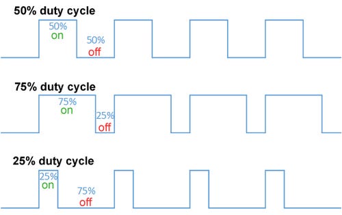
Outside of very cheap products, yes. In the 1940s and 1950s, we invented pulse width modulation. What is pulse width modulation? Well, at its simplest, it’s a way of turning the flow of power on and off very quickly, so that it’s only flowing for a set fraction of the time (the duty cycle).
This is a much more efficient way of controlling the current - averaged across time - flowing through the motor, because the switch dissipates almost no power when either fully off (because there’s no current) or fully on (because there’s no voltage across it), unlike a resistance.
And because the motor’s an inertial load, it keeps turning while the power is off, as long as you keep the total cycle length short and switch quickly enough. A DC motor, like the 24V spindle motor, running at a 50% duty cycle, thus behaves in practice just like a 24V spindle motor receiving 12V5, and obligingly runs at half speed.
You can also phrase duty cycle as “effective voltage”, which is the effective voltage the motor is getting averaged over time - for example, if we chop the whole cycle into four, a 50% duty cycle is effectively 24V + 24V + 0V + 0V / 4 = 12V, and a 25% duty cycle likewise 24V + 0V + 0V + 0V / 4 = 6V.
(I dislike this terminology because it obfuscates how PWM works underneath, but it’s generally accepted, so.)
About The Switch…
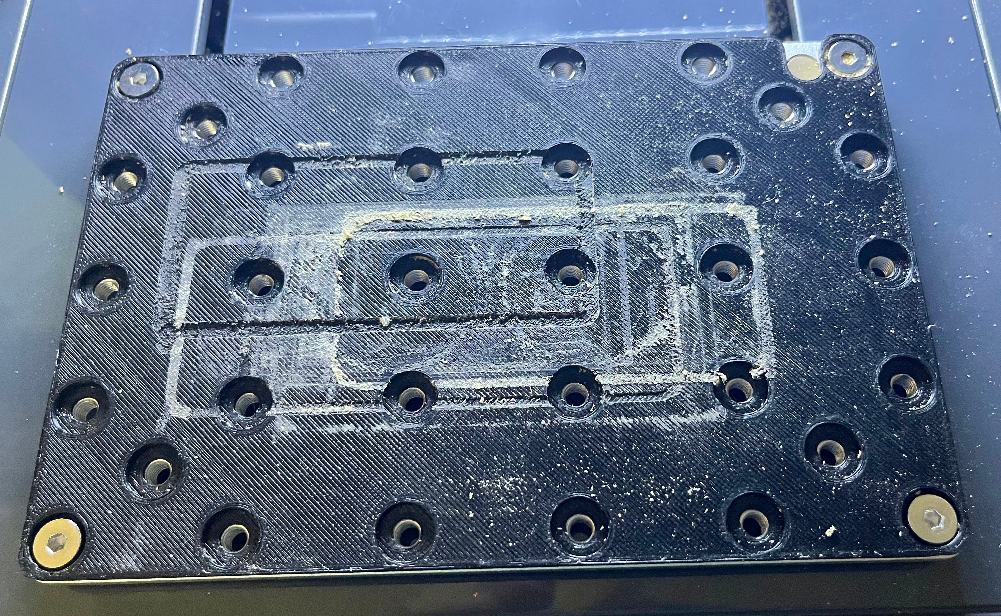
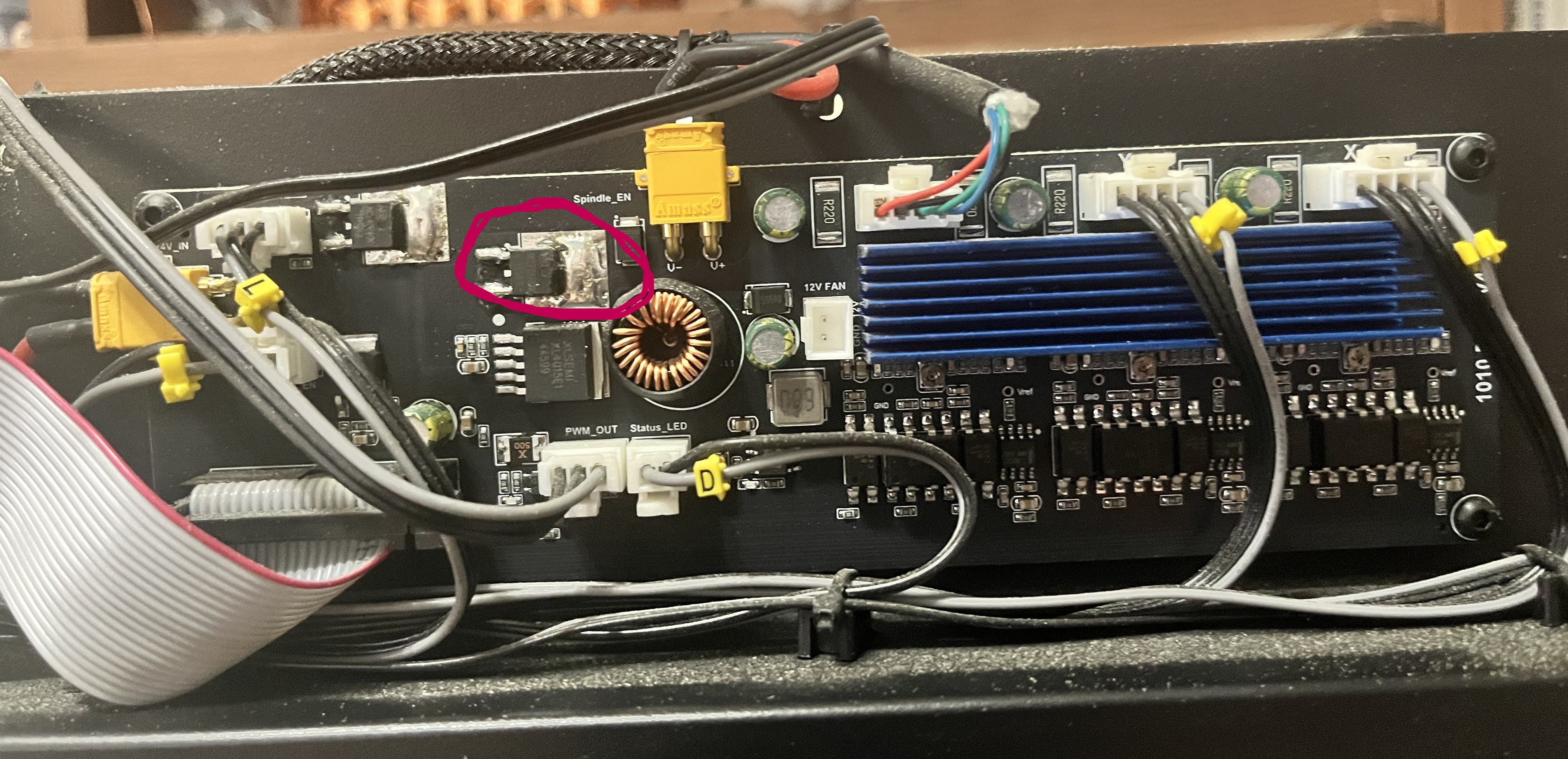
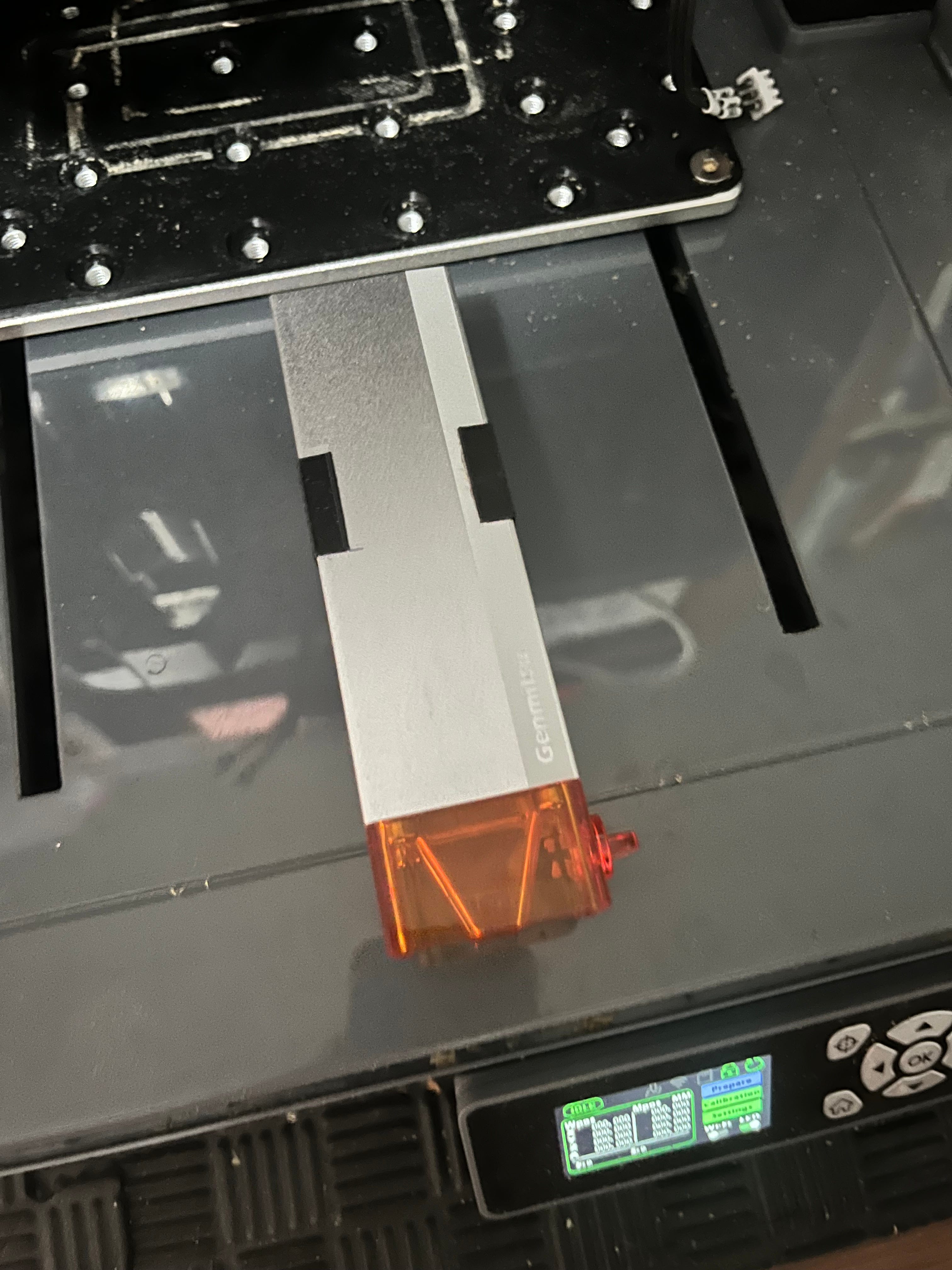
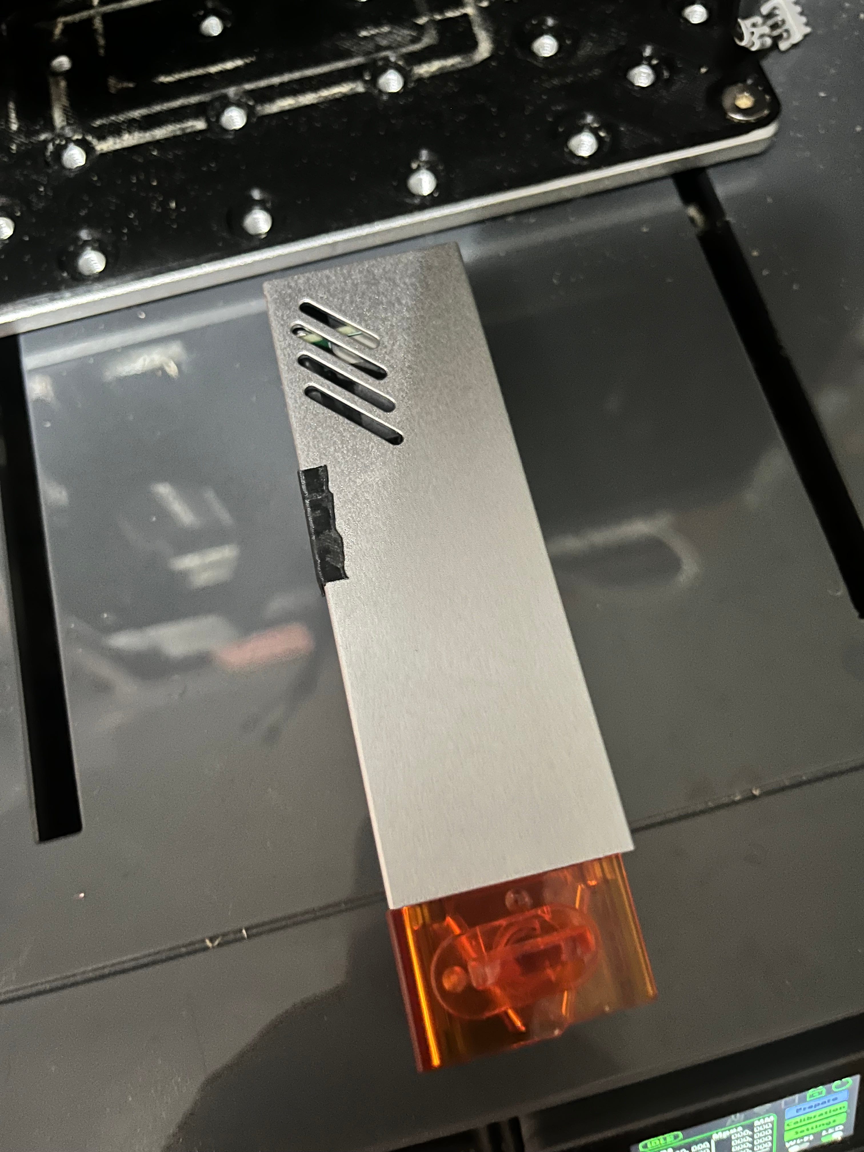
If you were wondering where the switch is…

…yes, it’s that MOSFET I talked about in a previous article.
To go into some details that will come in useful later: the microcontroller inside the Cubiko, which runs Grbl and controls the machine, does the actual work of providing a PWM signal at 5V on one of its pins.
This signal is then sent to two places. It is sent to the laser via its cable (you can see on the picture below the MOSFET a connector labeled “PWM_OUT”) to control it, which I’ll talk about later, and it is send to the circled MOSFET. The MOSFET then acts as a glorified switch, turning the 24V supply to the spindle on and off to match the signal it’s getting from the microcontroller.
And that’s how motor speed is controlled!
Bringing This Home To $30
If you’ve been following along, you may be wondering how it is that we get to set spindle speed in terms of rpm, since nothing on the electronics side of the spindle understands rpm. The answer is, as it so often is, approximations.
What the microcontroller can actually do is set the duty cycle of its PWM pin (and therefore, ultimately, the spindle power) to any of 256 discrete values6, from completely off (0V, all the time) to completely on (5V, and thus 24V at the spindle, all the time). In terms of “effective voltage”, that translates to 0.02V7 (0.1V at the spindle) increments.
People who do cybernetics for a living will chafe at the notion that we’re really “controlling” the spindle speed, insofar as it depends entirely on approximate fractions of the nominal speed of the spindle motor, and that it will inevitably slow down once placed under load since we don’t actually monitor its speed and vary the power supply to ensure that this doesn’t happen.
And they’re right to do so.
But much like, for example, the way that we don’t actually track the position of the axis steppers on 3D printers and low-end CNC machines but rather rely on dead reckoning, we’ve found that these approximations work well enough 99% of the time, and thus only the people who really need them should bother paying for the associated sensors and significantly more complex motor control circuits/algorithms.
Grbl has the job of transforming the spindle speed commands you send it into these 256 values. What $30 (maximum spindle speed) and $31 (minimum spindle speed) do is define a range of rpms which will be mapped onto a range of duty cycles, from completely on, to “lowest possible”8, 0 always being completely off.
So if you set $30 to 10000, such as it is for the default Cubiko spindle, requests for spindle speeds work out like this:
S10000 is 1.0 of $30; 1.0 of 255 is 255; 255/255 of 24V is 24V effective; 24V is 10,000 rpm nominal9
S9000 is 0.9 of $30; 0.9 of 255 is 229; 229/255 of 24V is 21.5V effective; 21.5V is 8,958 rpm nominal
S5000 is 0.5 of $30; 0.5 of 255 is 127; 127/255 of 24V is 11.9V effective; 11.9V is 4,958 rpm nominal
S2500 is 0.25 of $30; 0.25 of 255 is 63; 63/255 of 24V is 5.9V effective; 5.9V is 2,458 rpm nominal
S1000 is 0.1 of $30; 0.1 of 255 is 25; 25/255 of 24V is 2.3V effective; 2.3V is 958 rpm nominal
S0 is 0.0 of $30; 0.0 of 255 is 0; 0/255 of 24V is 0V effective; 0V is 0 rpm
The first thing you should note is that the numbers at the end are approximations of what you asked for. This is because there are only 255 gradations between $31 and $30, meaning that the smallest change in rpm the driver supports is $30/255 = 39.2 rpm. Essentially, the spindle speed space is divided up into bands 39.2 rpm across, and you’re going to get the speed of the band you land in, not the exact number you asked for.
The second thing you should note is that since the spindle speed you asked for goes through a process of being converted to voltage and back again via a series of mappings and approximations, it doesn’t necessarily have to map the “right” way.
The Land Of Really Bad Ideas
So what happens if you install the optional 20k spindle?
Well, if you’re smart, you set $30=20000, and then all the spindle speeds in your gcode still make sense.
Now S20000 means 24V rather than S10000, and the rpm “bands” are now 78.4 rpm wide instead of 39.2 rpm making your requests a little more approximate, but by and large, everything works the way you expect.
But what if you don’t? What if you leave $30 at 10000? What happens then?
…nothing, so far as the firmware is concerned. It doesn’t know that you’ve swapped out the spindle motor. But as the nominal speed of the new motor is 20,000 rpm at 24V instead of 10,000 rpm, your spindle will turn twice as fast as your gcode tells it to.
This may lead to broken bits, messed-up workpieces, and other assorted consequences, but the firmware won’t care. You’re just asking it to supply a given voltage and it’s doing that.
Can you do this intentionally? Sure, if you change all the spindle speeds in your gcode and in the design software that writes your gcode and in your head to reflect the twice-as-fast reality. You could also set $30 to 1000 with the regular spindle and treat all your numbers as 1/10th of what they should be, or set it to 255 and treat it as raw voltage increments.
Should you? Hell no. I’m only telling you this so you have a better understanding of what’s going on under the covers, and an easier time figuring out what went wrong if you accidentally forget to change $30.
So How Does This Work For Lasers?
Laser power is controlled by PWM, just like motor power.
This is actually more important for lasers than motors, since unlike motors, lasers work well at one voltage and can’t simply have their output power changed by varying the input voltage10. The simplest way you can control how much lasing you get is PWM: actually turning the laser off part of the time.
Conveniently, the drive board in the Cubiko already has a PWM circuit to run the spindle, so it takes the PWM signal from the microcontroller before it reaches the spindle MOSFET and uses that to tell the laser when to switch on and off. That’s what the third wire in the laser cable is for.
Now where the laser is concerned, forget all those “effective voltage” notions. Laser power is expressed simply in terms of the duty cycle. At 100% (i.e., on all the time), you’re getting the full power of the laser. 50% laser power means 50% duty cycle, halving the power-delivered-per-second. 25%, 10%, 1%, 0.25%, same principle. It’s still limited to the 256 different settings that Grbl and the microcontroller can deliver, so your laser power setting will be rounded into the nearest 0.4% band.
And This Interacts With The Spindle Settings How?
Because you use S-commands to set the laser power, just like you use them to set the spindle speed. They already exist, so we re-use them.
So when you have the laser installed, the numbers between $31 and $30 map onto the space between 0% and 100% for laser power. So, if you don’t change the default at all from the $30=10000 that the Cubiko’s configured for by default for its standard spindle, you get 100% laser power by sending S10000, 50% by sending S5000, 0.25% by sending S25, and so on.
In practice, though, you won’t see this because your laser software conveniently asks you for laser power in percentage terms. So how does it know what to ask for?
Yep. It maps laser power percentages to spindle speed requests so the firmware can map them back to duty cycle percentages and timings that the drive board can deliver to the laser, and if this sounds Rube Goldberg to you, you’re absolutely right to think so. It’s just that all these components were built by different people in different places and times, so occasionally things are less perfectly integrated that we, looking at them now, might prefer.
But to do this mapping, the laser software and the Cubiko firmware have to agree on what spindle speed represents 100% laser power.
Setting $30 For The Laser
The standard advice given is that when you install the laser module, you should - in addition to setting laser mode ($32=1)11 - set $30=1000.
This is not strictly correct. It will be correct much of the time because there’s a lot of laser software out there that defaults to using permille laser power in its S-commands, but what you actually need to ensure is that the software you’re using to generate and send gcode, and the Cubiko, have the same understanding of what $30 is.
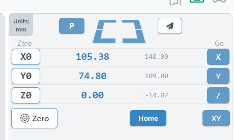
To pick one example, I use gSender to send the gcode for my milling jobs. In gSender, there is this control here which lets you select between spindle and laser mode:
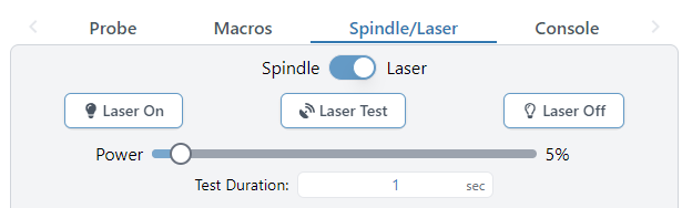
When you flip the switch to “Laser”, as you can see in the console tab, it sends the following commands:
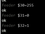
…meaning that 100% laser power is set with S255, and any gcode I was going to send to the laser using it - especially if it uses anything but full power - needs to be compiled accordingly.
What I actually use for laser work is LightBurn, and LightBurn lets you configure it to match the Cubiko, rather than the other way around. If you go into Device Settings in LightBurn, you’ll see this option:
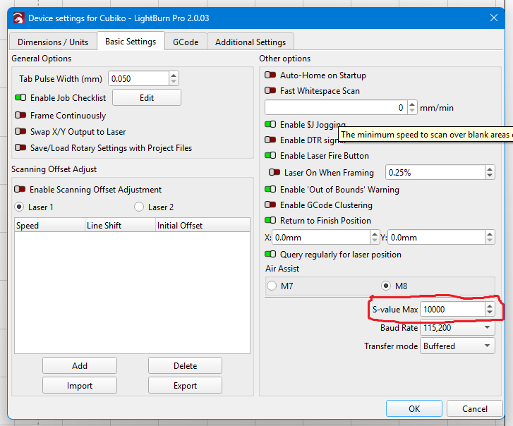
…”S-value Max”. What you need to do is set this to match the $30 value on your Cubiko, and LightBurn will generate its laser power S-commands to match. I have set it to 10000, as this way I don’t have to remember to change $3012 when I swap spindle for laser or vice versa.
To sum up: for the laser, it’s that they match that matters, not the absolute value. Find out how your software does it, and configure it and/or the Cubiko accordingly.
And That’s It
I hope you enjoyed, or at least found informative, this little trip down through the innard of motor and laser control on the Cubiko, and other similar machines. See you again next time!
This is obviously a huge simplification that applies as written to direct current motors, such as the Cubiko’s spindle motor, and not to either alternating current motors or stepper motors. Go with me here.
The relationship between current and speed isn’t perfectly linear for real-world motors, but it’s close enough.
So, around 1930.
If you have a suitably vintage sewing machine, this is how the pedal worked.
Although it does behave better if you expect it to start and run and slow speeds, since it is getting the full voltage - just not all the time.
Because binary.
In round numbers.
I can’t think of a reason offhand why you would set $31 to anything other than zero on the Cubiko or anything using a conventional DC motor, but if you do, any spindle speed between zero and $31 will get the lowest output, 0.02V effective, and the range between $31 and $30 will be mapped as above.
If you’re like me, you will instantly be asking “So what if I ask for a faster speed than $30?” The answer is: nothing more than if you had asked for $30. You can’t get more than everything, so you’ll take the full voltage available and like it, young man.
The reasons for this involve the energy levels of the electrons doing the lasing and quantum mechanics. I’m not a trained physicist, just a well-educated layman, but I could still ramble on about how this works for many paragraphs - but this post is long enough already, and doesn’t even have a margin.
This is very important, because what it does is turn off the pause between motion commands that change the spindle speed. (This pause exists because a spindle takes time to accelerate, and so not pausing for a moment to allow it to do so results in trying to cut with the spindle at the wrong speed or even stopped, which is a good way to break a bit. The laser, on the other hand, can start firing at full power immediately, so pausing with the laser installed means you get burned spots or possibly even fires.)
I have a couple of macros set up in LightBurn to toggle $32 for me.