A Tale of Two MOSFETs
In which things break, and I fix them, mod them, and do the other things.

(Many thanks go to Jan Roubal and Johnmichael Quinlan from the Genmitsu Cubiko Launch Group on Facebook for assistance received in solving the problems described, and thus indirectly in writing this article.)
Not because they are easy, but because they’re easier than the alternative.
Enough of this.
So, I’ve still been having fun making things with the Genmitsu Cubiko, and that fun continued right up until last Monday, when after one short milling job (around 45 minutes), the spindle didn’t stop running. Despite Gcode stop commands and the emergency stop button, and even powering off the machine only stopped it while the power was off. It started right up again when power was reapplied.
In short, I had a dead MOSFET.
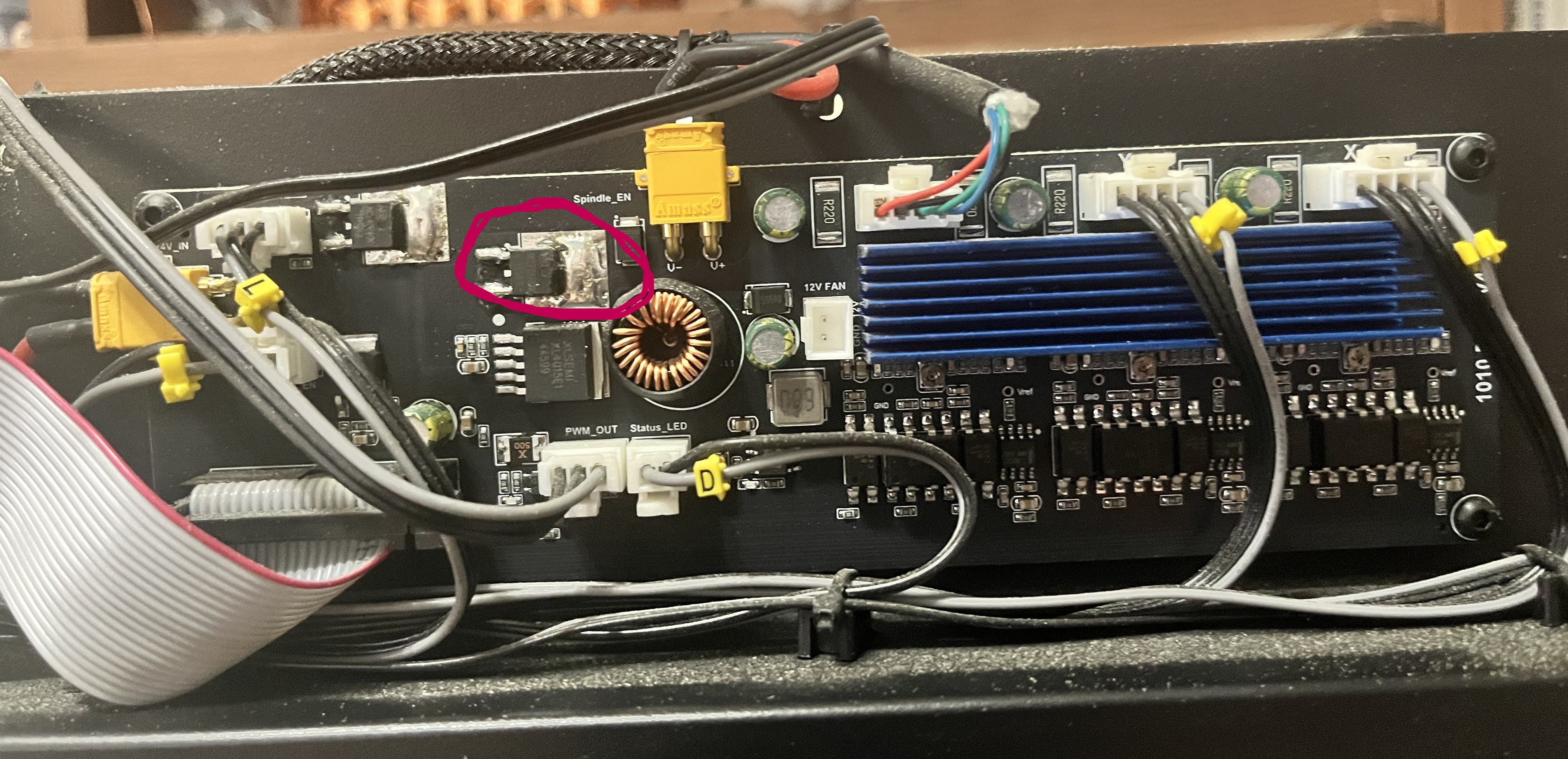
If you don’t know what a MOSFET is, it’s the circled widget in the picture above. It’s a transistor used to control the power supply to the spindle motor (which as you can see is plugged into the yellow XT30 connector just to the right of the circled MOSFET), and thus both whether it spins at all, in which direction, and how fast.
Unfortunately, when it gets too hot, it can fail, and when it fails, it fails “open”, meaning that power flows and the spindle just keeps running.
(I will mention at this point that, despite some suspicions, I don’t think that this is a design flaw with the Cubiko, mostly because even though it isn’t actively cooled, there’s a heat sink exactly opposite these two MOSFETs between the board and the folded steel chassis of the machine, and my failure was after a very short period of time in cool conditions, after many longer jobs had completed successfully.
In my opinion, it’s much more likely that some of we backers were just unlucky enough to get machines built with a batch of MOSFETs that were flaky from the factory. Good enough to pass QA, but with a temperature tolerance a lot narrower than it should have been. Sometimes bad part weeks just happen.
That being said, yes, I added extra cooling anyway. Belt and braces, belike.)
Here’s what I did, in case it’s of use to any of you with the same problem, or if you want to do any of it preemptively.
Starting the Process
First thing to do, obviously: disassemble the machine to be able to get at the drive board. This is very simple: just follow the process described in this video, courtesy of the manufacturer.
I will, however, tell you to have a whole lot of little trays available before you start, because this process produces a whole lot of screws, and you will need to keep them all sorted, separate, and in places they are not likely to fall off.
When you’re done, the drive board - as seen in the picture above - is the circuit board located running across the upper back of the machine, easily identifiable by having “1010 Drive V4.0” printed on the right-hand side.
I will also recommend at this point taking a photograph of the board, printing it out, and making yourself a neat map of where all the cables go using the handy yellow tags on them, because your next step is going to be carefully disconnecting them all, removing the four screws holding them in, and taking the drive board out, and when you’re done, you’re going to have to put all this back just the way it was before.
As you are removing it, you will have to pry the board (being sure not to bend it) off the heat sink behind the MOSFETs, to which it is attached with thermal tape. Be very careful, because you’re going to want to put it right back on there afterwards.
Don’t touch the control board on the left side of the machine (looking from the rear). You’re not doing anything with that.
The Book of MOSFET
The first thing you need to do, obviously, is remove and replace the failed MOSFET. For a replacement, this one from DigiKey (the IPD082N10N3GATMA1) does the job nicely. You only need one, so naturally I ordered two, just in case I broke one in the process. At $1.60 each (at the time of writing), it’s cheap insurance.
I also, at this time, ordered a couple of these V2016B heatsinks1. These are very small (8.5 mm x 8.5 mm) heatsinks just right for perching on top of a MOSFET for additional cooling, and since additional cooling never hurt anyone, we’re going to add them. You’ll need two of these, since just to the left of the spindle MOSFET, you’ll see another one that’s used to power the whole Cubiko on and off. We’re not replacing that one, but we might as well add some cooling to it just in case.
…I’m not going to tell you how to replace the MOSFET in detail. This is for two reasons - the first being that if you already know how to solder, you don’t need me to tell you, and if you don’t this is not the place to start out; and the second being that since this was my very first time working with surface-mount components, I’m the last person who should be trying to teach anyone else how to do it.
Suffice it to say that with the cunning use of solder wick and my trusty iron, I got the old one off the board and put the new one on with no more trouble than some vaguely irritating flux stains.
Having done this, take some thermal glue (I used this one) - normal glue will not work, since you need good thermal conductivity - put a dab of it on the bottom of the heatsink, and attach it to the top of the MOSFET. Do the same thing for the second heatsink and the power MOSFET we mentioned earlier. Allow forty minutes or so for the glue to dry enough to be secure, and you can put the board back in.
Hol(e)y Case, Batman!
Now, I could have stopped there.
But as it happened, I had a box of 12V 40mm fans (these ones) left lying around from earlier upgrades of a 3D printer2, so why not, I thought, add some active cooling? Especially since there’s a perfectly good 12V fan connector on the drive board currently going entirely unused3.
The first step in doing this is to make a place to mount it on the back of the case, which requires you to make some decisions. My first one was the most obvious: while many cooling fans function as exhaust fans, I decided to set up my Cubiko fan to blow air into the case. I chose this because, new hole aside, the other obvious air path out of the drive board compartment is the cable path over the top of the steel frame which leads to the working area of the machine, and it’s obviously better to have air moving in the direction that keeps dust and chips out of the electronics, rather than the one which draws them in.
(On the fans I had, this just involved taking the cable out of the existing strain relief and adding a drop of glue on the other side to take its place.)
I also decided to mount the fan on the outside of the existing case, rather than the inside. There was probably room in there for it, but it’s already crowded, so why make my job any harder than it needed to be?
You’re aiming for just left of midline, at the top of the upper part of the case. Drill from the outside4, or you won’t get it high enough.
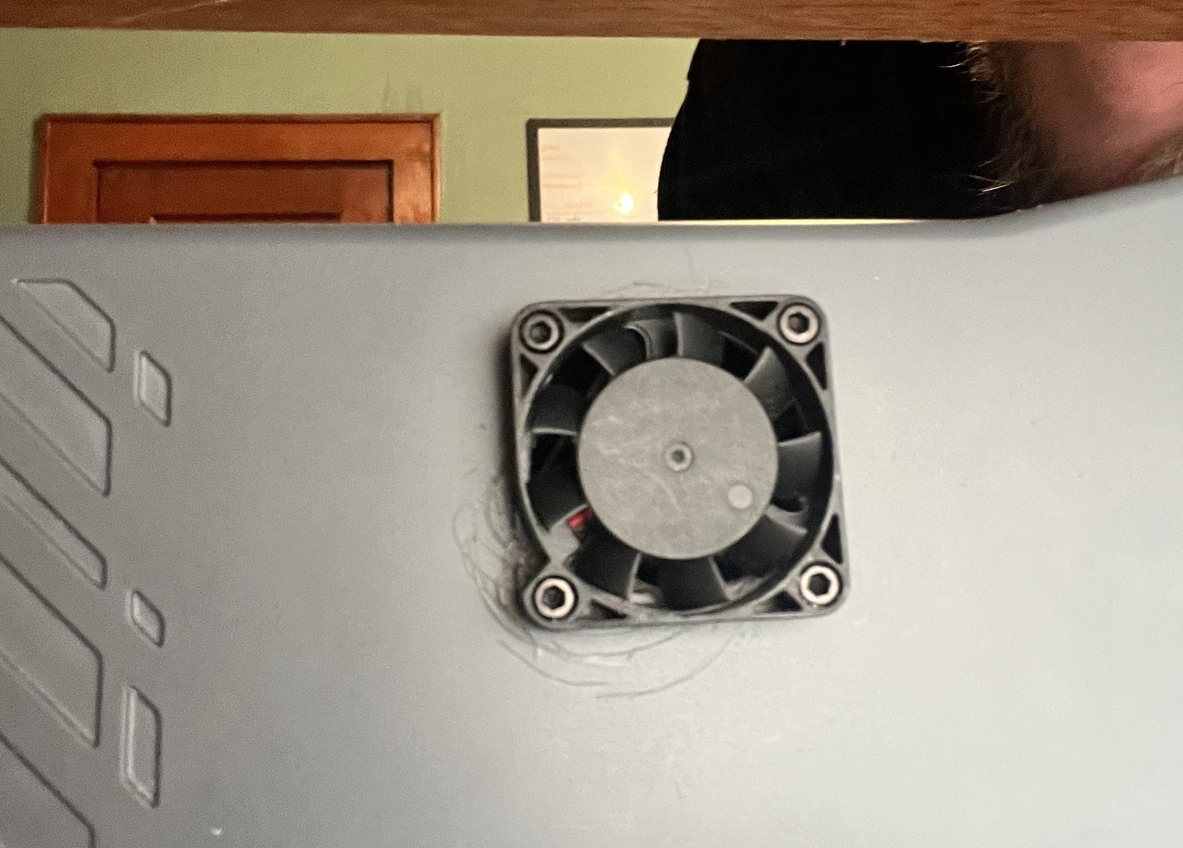
Don’t do what I did and try to use a hole-cutting bit to make your fan hole unless you are much better at it than me, since it will skip messily, promises of working well on “hard plastic” aside, and make a mess of your case. I ended up drilling a ring of holes with my screw-hole bit and using a Dremel to join them up and finish it off.
This also isn’t quite done; I’m going to 3D print a clip-on protective cover for the fan that will coincidentally also cover up the scratches.
Then just plug it in as you reassemble. Even a small (40 mm) fan like mine should provide a very satisfying flow of air out of the existing air hole in the back of the case when operating with the cover on.
And We’re Done
Test it’s all working, and then reassemble the machine. Preferably in that order, as taking it apart and putting it back together is kind of a pain.
And now you’ve fixed your MOSFET problem, and/or ensured that you won’t have a future MOSFET problem.
Excelsior!
These are $0.48 each (at the time of writing), but there is a $0.12 tariff each on importing these pinkie-nail-sized chunks of aluminium. And that’s all I’m going to say about that.
If you’re not buying new fans, and even if you are, make sure you check the voltage. A lot of current 3D printers use 24V fans these days, and there are also lots of 5V fans out there.
Make sure you also check the polarity of the fan wiring against that of this connector. My fans had plugs wired backwards vis-a-vis the board socket, so just plugging them in caused them to (a) not run and (b) get hot, which is the opposite of what you want. I had to cut and resplice the fan cable with the wires swapped over.
And, obviously, don’t put the case back on first.